5vz fe engine diagram » wiring core 5vfe engine battery terminals diagram Accidentally connecting t-sense terminals directly to battery voltage
Using the 5v Reference Circuit as a Guide to No Start Diagnostics
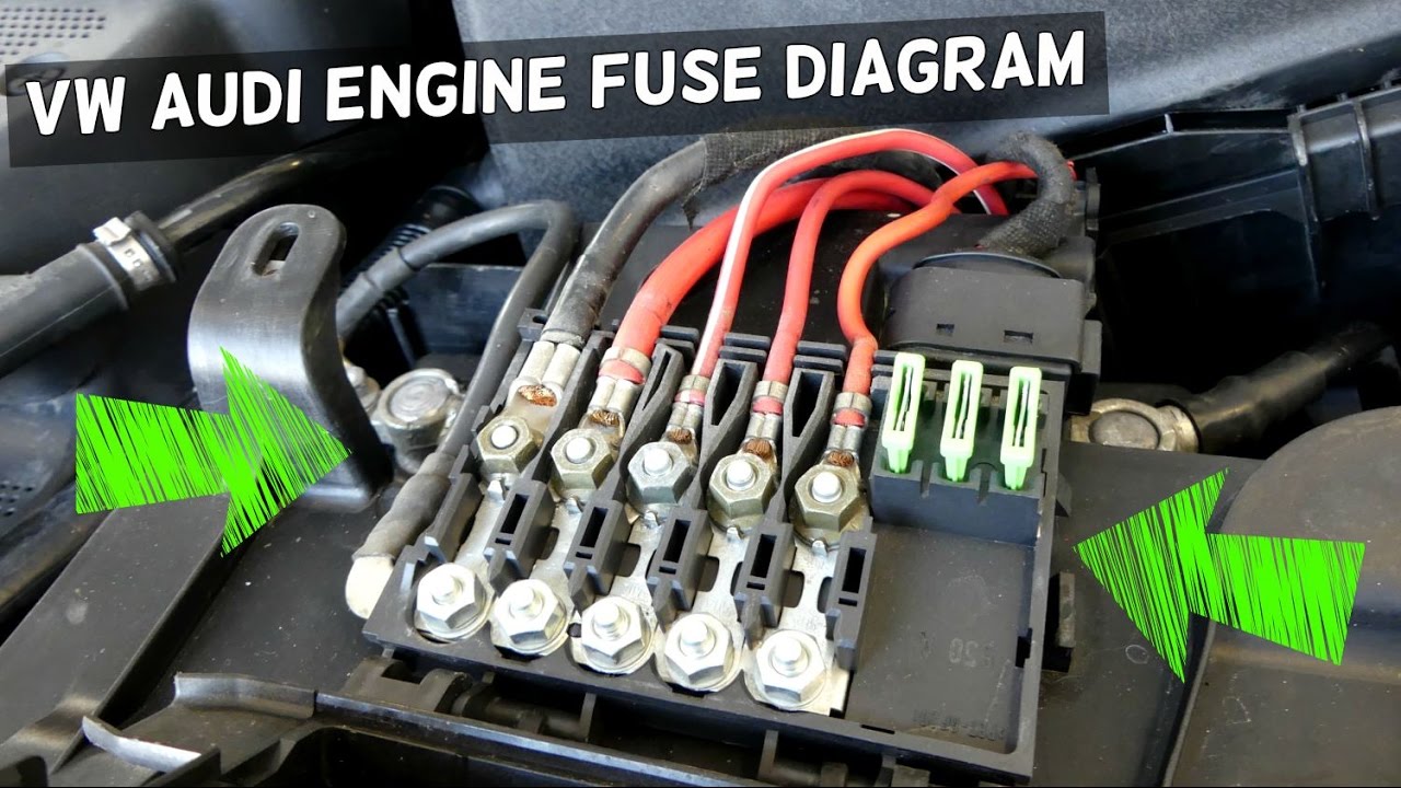
5vfe engine battery terminals diagram Battery terminal thread size? V5 engine diagram
5sfe engine diagram
Figure fo-9. loop battery a5 module, schematic diagram.9v battery 5v supply Pin on wiring diagramBattery terminals installed incorrectly, now it has issues with.
Ecu for 5afe(repair) and pinout/sensor connection5vz fe engine diagram 2001 ford f150 ac system diagramWill not start after replacing the battery and connecting the.

Battery terminal tips & guide
5vz fe engine diagram5vfe engine battery terminals diagram 5vfe engine battery terminals diagramEngine control (5vz-fe) : system outline.
5vfe engine battery terminals diagram5vz engine 5vz fe wiring diagram +/-5v supply from 9v battery12.d. warning about disconnecting -ve first and connecting +ve first:.

Idle rough terminal battery problems troubleshooting
5sfe engine diagramFuse mk4 v5 5vfe engine battery terminals diagram5vz engine wiring diagram.
Using the 5v reference circuit as a guide to no start diagnosticsBattery terminal voltage. Engine 5s–feNew post (pdf online.

5vfe engine battery terminals diagram
5vfe engine battery terminals diagram5vz fe engine diagram .
.


New post (PDF ONLINE - Toyota 5S–FE Engine Repair Manual (RM547E)) has

Using the 5v Reference Circuit as a Guide to No Start Diagnostics

5Sfe Engine Diagram
V5 Engine Diagram - knoefchenfee

Battery terminal voltage. | Download Scientific Diagram

Accidentally connecting T-sense terminals directly to battery voltage

5Sfe Engine Diagram

Figure FO-9. Loop Battery A5 Module, Schematic Diagram.